FLAGSHIP TRANSCEIVER Active MPN: COS13487EESA SOP-8 Package

COS13487EESA

500kbps Half-Duplex RS-485 / RS-422 Transceiver featuring Integrated Hardware Auto-Direction Control, Hot-Swap Protection, and 1/8-Unit Bus Loading (Up to 256 Nodes).
Request Sample & RFQ ↗ Download Datasheet (PDF) Request FAE & Free Samples
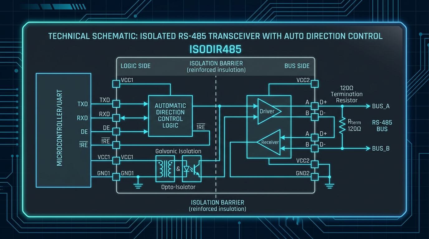
COS13487 Auto Direction Control RS-485 Transceiver Schematic

Verified Electrical Parameters

Supply Voltage Range 3.0V to 5.5V
Maximum Data Rate 500 kbps
Bus Unit Load 1/8 Unit (256 Nodes)
ESD Bus Protection ±15 kV HBM
Operating Temperature -40°C to +125°C

How Integrated Auto-Direction Control Simplifies PCB Design

Traditional RS-485 transceivers require an active microcontroller GPIO line to toggle the Driver Enable (DE) and Receiver Enable (/RE) pins. Timing errors in firmware can lead to bus contention, lost data packets, or complex software state machines. The COS13487EESA integrates an internal state machine that monitors data transitions on the DI pin and automatically manages driver and receiver states.

Traditional RS-485 Approach

  • Requires 3 optocouplers for isolated designs (TX, RX, DE).
  • Requires firmware GPIO timer interrupts to toggle direction.
  • Risk of bus driver overlap or missed turn-off windows.
  • Additional external pull-up/pull-down resistor networks.

COS13487EESA Auto-Direction Advantage

  • Only 2 optocouplers needed for full isolation (TX & RX).
  • Zero firmware overhead: Auto state machine handles switching.
  • Hot-swap protection: Prevents startup glitches on power-up.
  • Direct pin-compatible upgrade for standard SOP-8 sockets.

SOP-8 Pin Configuration & Description

Pin # Name Type Function & Description
1 RO Output Receiver Data Output. Connected to MCU UART RX.
2 CTRL Input Auto-Direction Control Pin. Pull HIGH to enable internal auto-direction state machine. Pull LOW for standard receive mode.
3 SHDN Input Shutdown Control Input. Pull HIGH for active operation. Pull LOW to enter ultra-low power shutdown mode.
4 DI Input Driver Data Input. Connected to MCU UART TX.
5 GND Power Ground reference connection.
6 A I/O Non-Inverting RS-485 Differential Bus Line.
7 B I/O Inverting RS-485 Differential Bus Line.
8 VCC Power Power Supply Voltage (3.0V to 5.5V). Decouple with 0.1µF ceramic capacitor to GND.

Engineer Design-In Checklist

  • ✓ Power Supply Voltage Confirm VCC is within 3.0V to 5.5V. Place a 100nF ceramic decoupling capacitor adjacent to Pin 8 and Pin 5.
  • ✓ Enable Auto-Direction Mode Tie Pin 2 (CTRL) and Pin 3 (SHDN) directly to VCC. The internal state machine will handle direction switching automatically.
  • ✓ Bus Termination & Failsafe Use a 120Ω termination resistor between A and B lines at both endpoints of the cable. Built-in failsafe ensures receiver RO defaults high on open/short.
  • ✓ Maximum Data Rate Limit Ensure your UART baud rate does not exceed 500 kbps (recommended for long-distance industrial cables up to 1200 meters).

Replacing MAX13487EESA or MAX485 in Existing Designs?

Verify pin compatibility, parametric deltas, and risk assessments using our interactive Competitor Cross-Reference tool.

Compare MAX13487EESA ↗ Request FAE Compatibility Review
SITEMAP