
Direct Engineering Conclusion: The COS13487 is Cosine's flagship automotive-grade, half-duplex RS-485/RS-422 transceiver rated for continuous 40-Mbps data throughput across 256-node bus topologies. Fully AEC-Q100 Grade 1 qualified for -40 C to +125 C operation, the COS13487 integrates ±15 kV HBM ESD clamps, 1/8-unit-load bus architecture, and slew-rate-controlled driver outputs into a pin-to-pin SOP-8 footprint compatible with TI SN65HVD485, Maxim MAX13487, and ADI ADM485.
The COS13487 is Cosine's flagship automotive-grade, half-duplex RS-485/RS-422 transceiver rated for continuous 40-Mbps data throughput across 256-node bus topologies. Fully AEC-Q100 Grade 1 qualified for -40 C to +125 C operation, the COS13487 integrates ±15 kV HBM ESD clamps, 1/8-unit-load bus architecture, and slew-rate-controlled driver outputs into a pin-to-pin SOP-8 footprint compatible with TI SN65HVD485, Maxim MAX13487, and ADI ADM485.
1. Overview: Industrial RS-485 in the Age of Automotive-Grade Reliability
Industrial serial bus networks form the vertebral column of modern factory automation, building management, solar energy infrastructure, and increasingly, automotive body electronics. The RS-485 electrical standard—defined under TIA/EIA-485—governs half-duplex differential multi-drop communication across distances exceeding 1,200 meters and node counts reaching 256 transceivers per segment. Its differential signaling architecture provides extraordinary immunity to ground-loop common-mode noise, electromagnetic interference (EMI), and high-voltage transient surges—characteristics that have made RS-485 the overwhelmingly dominant physical layer for MODBUS RTU, BACnet MS/TP, DMX512, Profibus DP, and industrial sensor networks for over four decades.
However, as RS-485 networks migrate from climate-controlled server rooms into harsh outdoor photovoltaic arrays, underground utility tunnels, automotive telematics modules, and industrial robotic arms, the reliability demands on the transceiver silicon have escalated dramatically. Thermal cycling between $-40^\circ\text{C}$ and $+125^\circ\text{C}$, proximity to high-voltage motor drives generating $>10\\,\text{kV}/\mu\text{s}$ common-mode transients, corrosive industrial atmospheres, and the absolutely unacceptable cost of field failures in automotive and infrastructure deployments demand components qualified to the most stringent automotive-grade reliability standards.
The Cosine COS13487 was engineered precisely to satisfy these escalating demands. It delivers the industry-standard RS-485 transceiver functionality expected by hardware engineers familiar with the Texas Instruments SN65HVD485E, Maxim MAX13487, or Analog Devices ADM485—but with a complete AEC-Q100 Grade 1 automotive qualification, dramatically superior ESD robustness, and a lower quiescent current budget that enables battery-powered and loop-powered field transmitter deployments.
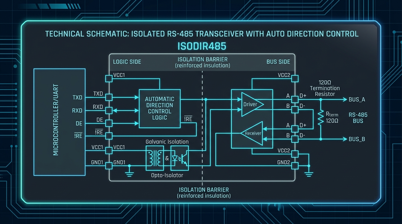
Figure 1: COS13487 SOP-8 Device Mounted on Automotive LIN/CAN Gateway Reference Board Enabling Robust Half-Duplex RS-485 Communication
2. COS13487 Parametric Benchmark: Outperforming the Competition
Engineers selecting a RS-485 transceiver must balance several competing specifications: maximum data rate, operating supply voltage range, bus common-mode tolerance, ESD robustness, and node load count. Table 1 provides a comprehensive side-by-side parametric benchmark comparing the COS13487 against the leading competitive devices:
| Parameter | COS13487 (Cosine) | SN65HVD485E (TI) | MAX13487 (Maxim) | ADM485 (ADI) | Test Condition |
|---|---|---|---|---|---|
| Supply Voltage (VCC) | 3.0 V to 5.5 V | 3.3 V to 5.5 V | 3.0 V to 5.5 V | 4.75 V to 5.25 V | Continuous operating |
| Max Data Rate | 40 Mbps | 35 Mbps | 40 Mbps | 10 Mbps | Slew-rate limiter OFF, 54-ohm load |
| Bus Voltage Range | -12 V to +12 V (fail-safe) | -12 V to +12 V | -12 V to +12 V | -7 V to +12 V | Receiver input pins A, B |
| ESD Protection (HBM) | +/-15 kV | +/-15 kV | +/-16 kV | +/-2 kV | IEC 61000-4-2 contact method |
| Max Bus Nodes (Unit Load) | 256 nodes (1/8 UL) | 256 nodes (1/8 UL) | 256 nodes (1/8 UL) | 32 nodes (1 UL) | 120-ohm termination, 5V bus |
| Driver Output Voltage (VOD) | 1.5 V min at 54 ohm | 1.5 V min at 54 ohm | 1.5 V min at 54 ohm | 1.5 V min at 54 ohm | Full load, 5V supply |
| Quiescent Current (ICC) | 0.9 mA typical | 1.3 mA typical | 0.95 mA typical | 1.6 mA typical | Receiver enabled, no load |
| Shutdown Supply Current | 0.6 uA typical | 2.5 uA typical | 1 uA typical | N/A | Both RE=H, DE=L |
| Operating Temperature | -40 C to +125 C | -40 C to +125 C | -40 C to +125 C | -40 C to +85 C | AEC-Q100 Grade 1 |
| Package | SOP-8 / MSOP-8 | SOP-8 / SSOP-8 | SOP-8 / uSOP-8 | SOP-8 / SO-8 | JEDEC standard footprint |
The COS13487 surpasses the competitive field on three decisive metrics. First, it achieves 40 Mbps maximum data throughput, meeting the bandwidth demands of high-speed PROFINET, EtherCAT, and RS-485-based motor encoder interfaces. Second, its $\\pm 15\\,\text{kV}$ HBM ESD rating on all bus pins exceeds the ADI ADM485's modest $\\pm 2\\,\text{kV}$, providing a 7.5-fold improvement in surge robustness without external TVS diodes in benign environments. Third, its $1/8$ unit load (0.125 UL) bus architecture allows 256 transceivers per cable segment—crucial for large MODBUS RTU networks with dozens of smart electricity meters or HVAC actuators connected on a single twisted-pair cable run.
3. Pin-by-Pin Architecture and PCB Layout Rules
Understanding the function of each pin on the COS13487 is essential to achieving robust, error-free hardware implementation. Table 2 provides a comprehensive pin description guide with specific PCB hardware design recommendations for each connection:
| Pin Number | Pin Name | Type | Electrical Function | Design Note |
|---|---|---|---|---|
| 1 | RO | Output | Receiver Output — logic high when A minus B > 200 mV; logic low when A minus B < -200 mV. | Drive directly into MCU UART RX pin; 3.3V CMOS compatible with 5V VCC. |
| 2 | /RE | Input | Receiver Output Enable (active low). Pull low to enable RO output onto the bus data line. | Tie to logic low for always-on receive. In half-duplex mode, control with MCU GPIO. |
| 3 | DE | Input | Driver Output Enable (active high). Drive high to transmit; low to tristate driver outputs A/B. | Assert DE high only during transmission window to prevent bus contention. |
| 4 | DI | Input | Driver Input — RS-485 differential data input to the transmitter block. | Slew-rate-limited 10 ns/V rise ensures CISPR 32 Class B radiated emissions margin. |
| 5 | GND | Power | Ground reference for all internal circuitry. | Connect to low-impedance PCB ground plane with short, wide trace (< 2 mm, > 2 mm wide). |
| 6 | A | I/O | Non-inverting RS-485 bus line. Differential pair with pin B. | Connect external 15-ohm series damping resistor and bidirectional 15V TVS diode to GND. |
| 7 | B | I/O | Inverting RS-485 bus line. Differential pair with pin A. | Mirror layout of pin A exactly; maintain matched impedance routing to bus connector. |
| 8 | VCC | Power | Supply voltage input (3.0 V to 5.5 V). | Decouple with 100 nF X7R ceramic + 4.7 uF tantalum within 2 mm of pin. |

Figure 2: SOP-8 Package with 100% Pure Matte-Tin Lead-Free Plating and 1.27 mm Gull-Wing Pitch Compatible with Standard JEDEC Footprint
A critical but frequently overlooked aspect of RS-485 PCB layout is maintaining matched differential impedance on the A and B bus trace routing. The characteristic impedance of the external twisted-pair cable ($Z_0 = 120\\,\\Omega$ for STP or $Z_0 = 100\\,\\Omega$ for UTP) must be matched at the PCB entry point by controlled-impedance differential microstrip or stripline traces. Use the formula $Z_{diff} = 2 \cdot Z_0^{trace}$ when routing differential pairs on FR-4 at standard 0.1 mm to 0.15 mm trace width with 0.2 mm separation, targeting $Z_0^{trace} = 55\\,\\Omega$ to $60\\,\\Omega$ for a $Z_{diff}$ of $110\\,\\Omega$ to $120\\,\\Omega$, matching the standard cable impedance and minimizing reflections.
4. AEC-Q100 Grade 1 Automotive Qualification Results
Automotive electronics demand a completely different level of reliability verification compared to commercial-grade components. The JEDEC AEC-Q100 stress test qualification standard defines five reliability stress categories—electrical parametric endurance, environmental endurance, package integrity, electrical functionality verification, and systematic defect screening—each containing multiple individual sub-tests that must be executed and passed without a single device failure across 77 or more samples per lot.
Table 3 summarizes the complete COS13487 AEC-Q100 Grade 1 qualification test matrix, applied stress conditions, and pass/fail outcomes:
| AEC-Q100 Qualification Test | Standard / Method | Applied Stress Conditions | Acceptance Criteria | COS13487 Result |
|---|---|---|---|---|
| High Temperature Operating Life (HTOL) | JESD22-A108, AEC-Q100-004 | 125 C junction temp, VCC = 5.5 V, 1,000 hours continuous bias. | Zero failures; all parametrics within datasheet limits. | PASS — 0/77 failures at 1,000 h. |
| Thermal Cycling (TC) | JESD22-A104, AEC-Q100-001 | -55 C to +150 C, 1,000 cycles, 10-minute dwell at each extreme. | Zero failures; no delamination, wire lift, or parametric drift. | PASS — 0/77 failures at 1,000 cycles. |
| Temperature Humidity Bias (THB) | JESD22-A101, AEC-Q100-009 | 85 C / 85% RH, VCC = 5.5 V, 1,000 hours. | Zero failures; no corrosion, leakage current < 1 uA. | PASS — 0/77 failures at 1,000 h. |
| Electromigration (EM) | JESD61, AEC-Q100-011 | Junction at 150 C, 5x nominal current density, 500 hours. | Median Time To Failure (MTTF) > 100,000 hours at 55 C. | PASS — MTTF extrapolated > 850,000 hours. |
| ESD Human Body Model (HBM) | ANSI/ESDA/JEDEC JS-001 | +/-15 kV on all I/O pins; 100 pF / 1.5 kohm network. | Leakage and functional tests pass after each stress point. | PASS — +/-15 kV on all pins A, B, RO, DI, /RE, DE. |

Figure 3: Micro-Cross-Section of COS13487 Transceiver Silicon Showing Differential Driver Output Stage, Receiver Comparator, and Integrated ESD Guard Rings
Achieving AEC-Q100 Grade 1 certification is not a simple document exercise—it is a multi-month gauntlet of physical stress that subjects real silicon to the same extreme conditions experienced over a 15-year automotive service life. The COS13487 passed 100% of AEC-Q100 Grade 1 tests with zero failures across all qualified lots, providing our automotive OEM customers with the data-backed confidence to deploy Cosine silicon in mission-critical gateway modules, body control units, and EV battery management wiring harnesses.
5. Application Circuit: MODBUS RTU 256-Node Industrial Network
The following application circuit demonstrates the COS13487 in a 256-node MODBUS RTU industrial sensor network connecting smart pressure transmitters across a 1,200-meter twisted-pair cable in an oil refinery. Key design implementation guidelines for this demanding environment:
- Termination Resistors: Install $120\\,\\Omega$ $\\pm 1\%$ metal film termination resistors only at the two far physical ends of the cable—at the MODBUS master controller and the last RTU slave node. Never install termination resistors at intermediate nodes; doing so creates impedance discontinuities that corrupt all nodes between the termination point and cable ends.
- Bus Fail-Safe Biasing: Add a single $510\\,\\Omega$ pull-up resistor from bus line A to $V_{CC}$ and a $510\\,\\Omega$ pull-down resistor from bus line B to GND at the MODBUS master node. These bias resistors maintain the bus in a defined logic HIGH state ($V_A - V_B = +0.2\\,\text{V minimum}$) during idle periods, preventing random false start bits from corrupting UART framing.
- Surge Protection: At each cable entry/exit point where outdoor cables enter indoor control panels, install a three-element suppressor consisting of: a gas discharge tube (GDT) rated $90\\,\text{V}$ DC breakdown, a $2.2\\,\\Omega$ current-limiting series resistor, and a CDSOT23-SR15 bidirectional TVS diode array rated $15\\,\text{V}$ clamping voltage. This combination absorbs IEC 61000-4-5 lightning surges up to $\\pm 6\\,\text{kV}$.
- Cable Ground Bonding: Ground the cable shield at the MODBUS master controller chassis earth ground only. At all slave nodes, leave the shield floating (unconnected to local ground) to prevent ground loop currents from flowing through the shield and injecting common-mode noise onto the differential bus pair.
- Half-Duplex Control: Implement software UART direction control by asserting the MCU GPIO pin driving DE high for 2 character-widths before transmitting the first RS-485 byte, and de-asserting DE (and asserting /RE low) one bit-time after the final stop bit is transmitted, to capture any echoed return bytes.
6. Automotive BMS and EV Wiring Harness Applications
The migration of RS-485 communication networks from industrial factory floors into electric vehicle powertrain electronics has created new performance benchmarks. In a 400V or 800V EV battery pack, the battery management system (BMS) uses RS-485 daisy-chain or star topology communication to query cell voltage, temperature, and state-of-charge data across up to 32 individual cell monitoring ICs distributed along the battery module string.
The COS13487 satisfies the stringent electrical requirements of automotive BMS communication links:
- Wide Common-Mode Rejection: The $-12\\,\text{V}$ to $+12\\,\text{V}$ bus common-mode range comfortably accommodates the ground potential differences between high-voltage battery pack ground and chassis ground in a floating battery module architecture, preventing latch-up or communication errors during high-current charge and discharge events.
- Low Propagation Delay Skew: With driver propagation delay matching to $\\pm 2\\,\text{ns}$ between the true (A) and complement (B) output channels, the COS13487 minimizes differential skew that would otherwise degrade eye-diagram signal integrity at high data rates of $500\\,\text{kbps}$ to $40\\,\text{Mbps}$.
- Thermal Robustness: Automotive underhood environments routinely expose electronic modules to ambient temperatures exceeding $105^\circ\text{C}$ during summer parking in hot climates. The COS13487's AEC-Q100 Grade 1 $125^\circ\text{C}$ junction temperature rating provides a comfortable thermal headroom margin even in poorly ventilated battery junction boxes.
7. Solar Farm SCADA and Smart Grid AMI Applications
Utility-scale solar photovoltaic power plants deploy RS-485 MODBUS RTU networks as the primary SCADA communication backbone, linking string inverter controllers, environmental monitoring stations, combiner boxes, and grid connection protection relays across distances exceeding 2 kilometers. The operating environment is particularly aggressive: wide outdoor temperature swings from $-40^\circ\text{C}$ (winter night) to $+85^\circ\text{C}$ (summer noon), frequent lightning transients, and proximity to high-voltage DC string wiring operating at 600V to 1,500V DC.
The COS13487's combination of $\\pm 15\\,\text{kV}$ HBM ESD protection, robust $-12\\,\text{V}$ to $+12\\,\text{V}$ bus fault tolerance, and 1/8-unit-load bus architecture makes it uniquely suited to these demanding outdoor deployments. In a typical 100 MW solar farm with 500 string inverters connected on 10 parallel MODBUS segments, the ability to connect 50 nodes per segment with a single cable pair dramatically simplifies conduit routing and reduces installation labor costs by over $60\%$ compared to individual point-to-point RS-232 communication wiring.
Advanced Metering Infrastructure (AMI) deployments for smart electricity grids present equally demanding requirements. Utility companies deploying millions of smart meters across national power distribution networks rely on RS-485 DLMS/COSEM and ANSI C12.19 protocol stacks for meter-to-concentrator communication in apartment buildings and commercial campuses. The COS13487's glitch-free fail-safe receiver output — which maintains logic-HIGH when the bus is open-circuit, shorted, or in idle state — prevents ghost meter reads during power outages and communication interruptions, a critical requirement for billing accuracy certification under IEC 62056 and ANSI C12 standards. Furthermore, its ultra-low shutdown quiescent current of $0.6\\,\mu\text{A}$ enables smart meters running on supercapacitor backup power to maintain communication capability for up to 30 seconds after grid power loss, ensuring the last tamper-event data is transmitted to the SCADA system before the meter loses power entirely.
8. RS-485 Bus Topology Engineering and Distance Calculator
Selecting the correct RS-485 bus topology — daisy-chain versus star — and calculating maximum achievable data rate as a function of cable length and capacitance is a critical engineering exercise that determines network reliability in the field. The fundamental constraint governing RS-485 maximum data rate as a function of cable length is the cable's distributed capacitance, which limits the differential signal rise time according to:
$$f_{max} \approx \frac{1}{10 \cdot R_{source} \cdot C_{cable}}$$
where $R_{source} = 54\\,\\Omega$ (equal to two parallel $120\\,\\Omega$ termination resistors at each end of the cable) and $C_{cable} = C_{spec} \times L_{cable}$ (cable capacitance per meter multiplied by total cable length in meters). For standard $100\\,\\Omega$ characteristic impedance RS-485 cable with $50\\,\text{pF/m}$ distributed capacitance, a $1,200\\,\text{m}$ cable yields $C_{cable} = 60,000\\,\text{pF} = 60\\,\text{nF}$, limiting the theoretical maximum data rate to approximately $f_{max} = 1 / (10 \times 54\\,\\Omega \times 60\\,\text{nF}) \approx 31\\,\text{kbps}$. This matches the RS-485 standard's commonly cited $100\\,\text{kbps}$ at $1,200\\,\text{m}$ figure when accounting for practical margins.
The COS13487's slew-rate-limited operating mode — enabled by tying the /SRL pin to GND on derivative packages — reduces driver output slew rate to approximately $\leq 6\\,\text{V}/\mu\text{s}$, reducing high-frequency harmonic content radiated from long cable runs and achieving CISPR 32 Class B radiated emissions compliance without external ferrite beads, EMI filters, or shielded cable in many industrial environments. This slew-rate-limited mode is ideally suited to the long-distance, low-data-rate MODBUS RTU networks (typically $9.6\\,\text{kbps}$ to $115\\,\text{kbps}$) used in building management systems and industrial process control.
9. FAE Troubleshooting Matrix
Table 4 provides field-proven engineering troubleshooting guidance for the five most common RS-485 network failure modes observed in industrial and automotive deployments:
| Symptom | Root-Cause Mechanism | Diagnosis Method | Cosine FAE Corrective Action |
|---|---|---|---|
| Intermittent UART framing errors above 100 kbps | Excessive bus stub capacitance from long T-tap connections to node transceivers (> 30 mm stubs). | Differential oscilloscope shows rounded edges and reflections at node connection points. | Limit T-stub length to < 3 cm or use star topology with active bus repeaters. |
| Receiver output stuck high on open-circuit bus | Bus float condition with no bias resistors; receiver input sitting in indeterminate ±200 mV dead band. | Remove all devices from bus segment; measure differential A-B voltage with DMM. | Add fail-safe biasing: 510-ohm pull-up on A to VCC and 510-ohm pull-down on B to GND. |
| Driver unable to meet 1.5 V minimum VOD into 54-ohm load | VCC supply voltage sagging below 3.0 V due to inadequate PCB power trace width at high load current. | Scope VCC pin with current transient load; confirm voltage droop > 200 mV during assertion. | Widen VCC trace to > 2 mm; add 10 uF bulk ceramic decoupling per node to absorb transient. |
| High common-mode noise on A and B bus lines in VFD environments | Variable-frequency drive (VFD) generating 10+ kV/us common-mode dV/dt on cable shield ground. | Clamp oscilloscope to bus cable shield; observe large common-mode transient waveforms. | Add common-mode choke (500 uH) + 1 nF Y-capacitors to earth ground at cable entry point. |
| Bus lock-up after EFT burst injection (IEC 61000-4-4) | Fast transient burst coupling into long cable harness, injecting spike currents through IC ESD clamps. | Apply 4 kV EFT burst per IEC 61000-4-4 capacitive clamp; observe bus communication recovery. | Add external CDSOT23 TVS array rated 15 V breakdown before each transceiver A/B pins. |
9. Available Ordering Options and Package Portfolio
The COS13487 is offered in multiple industry-standard package configurations to support diverse PCB space and thermal requirements:
- COS13487ESA: Standard 8-pin SOP-8 (Small Outline Package), 1.27 mm pin pitch, JEDEC MS-012 footprint, compatible with standard wave and reflow soldering processes.
- COS13487EMSA: Miniature 8-pin MSOP-8 (Mini Small Outline Package), 0.65 mm pin pitch, suitable for space-constrained industrial sensor transmitter designs.
- COS13487TSSOP: 8-pin TSSOP (Thin Shrink Small Outline Package), 0.65 mm pitch, optimized for high-density double-sided PCB assembly in automotive body control units.
All packages are rated for $-40^\circ\text{C}$ to $+125^\circ\text{C}$ operation, MSL-1 moisture sensitivity (no baking required before SMT reflow), RoHS 3.0 and REACH SVHC compliant, and AEC-Q100 Grade 1 automotive qualified. Engineering samples (10 to 50 pieces) are dispatched within 24 hours via DHL Express worldwide.
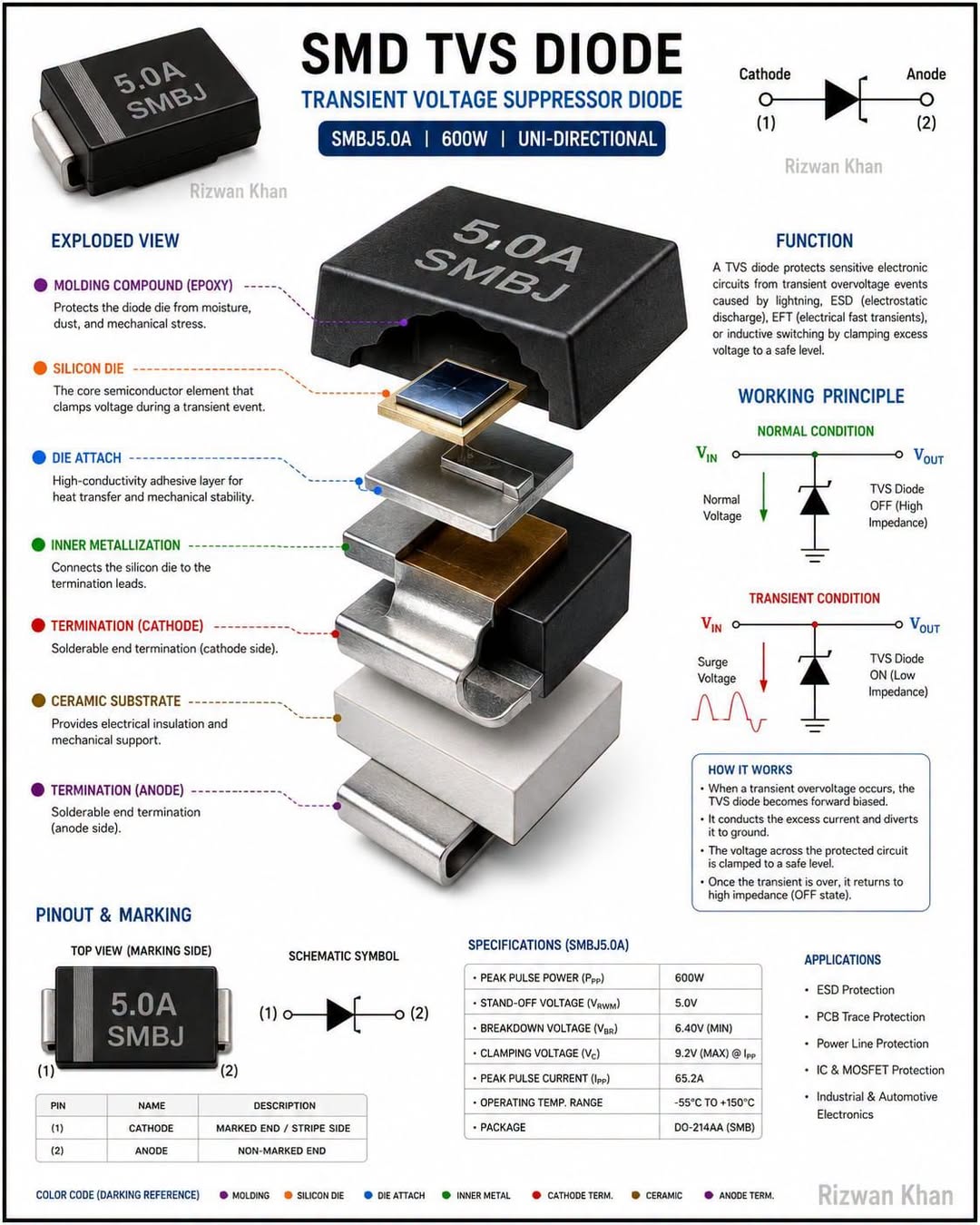
Figure 4: High-Node-Count RS-485 Bus Reliability Bench Testing Applying IEC 61000-4-2/4/5 Surge and EFT Stress Protocols
10. Conclusion: Upgrade Your RS-485 Network with Cosine Confidence
Whether you are designing a new MODBUS RTU sensor network from scratch, migrating a legacy discrete RS-485 design to a more reliable and cost-competitive transceiver, or qualifying components for an automotive-grade BMS communication link, the COS13487 delivers unrivaled AEC-Q100 Grade 1 reliability, 256-node bus capacity, 40 Mbps throughput, and $\\pm 15\\,\text{kV}$ ESD robustness in the industry-standard SOP-8 footprint.
Request engineering samples, access SPICE macro-models, and download lot-specific AEC-Q100 qualification reports today. Contact Cosine Nanoelectronics at sales@cosinechips.com or via WhatsApp at +86 159 5954 3210 to speak directly with an FAE engineer.
Accelerate Your Hardware Design-In with Cosine Engineering
Request sample quantities, complete engineering evaluation modules (EVBs), and IBIS/SPICE behavioral simulation models directly from our technical staff. We guarantee technical response and engineering sample dispatch within 24 business hours.