
Direct Engineering Conclusion: The COS485 (5V) and COS3485 (3.3V) are high-reliability, half-duplex RS-485/RS-422 transceivers designed for continuous 10-Mbps data throughput in harsh industrial environments. They are drop-in compatible with the MAX485, MAX3485, and SN75176B. Featuring ±15 kV ESD protection, 1/8 unit load allowing up to 256 nodes, and an extended -7V to +12V bus range, they offer superior signal integrity for MODBUS RTU, BACnet MS/TP, and DMX512 applications.
The COS485 (5V) and COS3485 (3.3V) are high-reliability, half-duplex RS-485/RS-422 transceivers designed for continuous 10-Mbps data throughput in harsh industrial environments. They are drop-in compatible with the MAX485, MAX3485, and SN75176B. Featuring ±15 kV ESD protection, 1/8 unit load allowing up to 256 nodes, and an extended -7V to +12V bus range, they offer superior signal integrity for MODBUS RTU, BACnet MS/TP, and DMX512 applications.
1. Introduction to COS485 and COS3485
Industrial serial bus networks are the backbone of modern factory automation, building management, and energy infrastructure. The RS-485 electrical standard governs half-duplex differential multi-drop communication across distances exceeding 1,200 meters. The COS485 (5V) and COS3485 (3.3V) are robust RS-485 transceivers optimized for high-reliability data transmission in industrial environments. They offer 10 Mbps maximum data rates and incorporate strong $\\pm 15\\,\text{kV}$ ESD protection, ensuring exceptional longevity in harsh deployments.
These devices are direct, drop-in replacements for the ubiquitous MAX485, MAX3485, and SN75176B transceivers, giving hardware engineers a simple upgrade path to achieve 256-node network capabilities and significantly superior surge immunity. Their differential signaling architecture provides extraordinary immunity to ground-loop common-mode noise and electromagnetic interference (EMI).

Figure 1: COS485 SOP-8 Device Mounted on Industrial Gateway Board for RS-485 Communication
The COS485 and COS3485 are perfectly suited for long-distance, multi-drop systems such as MODBUS RTU, BACnet MS/TP, DMX512 lighting networks, and industrial process control applications where reliability is non-negotiable.
With an extensive operating temperature range and robust electrical characteristics, the COS485/COS3485 transceivers ensure continuous communication in environments subject to severe electrical transients. They have become the industry standard for RS-485 upgrades across global factory floors. The COS485/COS3485 transceivers are built on an advanced sub-micron BiCMOS process, allowing them to deliver both high-speed performance and exceptional robustness in a compact footprint. This deep engineering approach guarantees minimal skew and excellent duty cycle matching, critical for high-speed protocols. The devices also feature thermal shutdown circuitry, which prevents damage from bus contention or severe output short-circuits. Their robust receiver inputs can withstand extended common-mode voltages, guaranteeing continuous data integrity even when severe ground potential differences exist across a sprawling industrial plant. Furthermore, the transceivers incorporate fail-safe circuitry that guarantees a logic-high receiver output when the receiver inputs are open, shorted, or idle, eliminating the need for external bias resistors on the bus.
2. Parametric Benchmark Analysis
When selecting a transceiver for RS-485 networks, engineers evaluate maximum data rate, supply voltage, bus common-mode tolerance, ESD robustness, and bus load count. The table below benchmarks the COS485 and COS3485 against popular industry alternatives.
| Parameter | COS485 / COS3485 | MAX485 / MAX3485 | SN75176B | ADM485 | Test Condition |
|---|---|---|---|---|---|
| Supply Voltage (VCC) | 4.75-5.25V / 3.0-3.6V | 4.75-5.25V / 3.0-3.6V | 4.75-5.25V | 4.75-5.25V | Operating |
| Max Data Rate | 10 Mbps | 2.5 Mbps / 10 Mbps | 10 Mbps | 5 Mbps | Full load |
| Bus Voltage Range | -7 V to +12 V | -7 V to +12 V | -7 V to +12 V | -7 V to +12 V | Inputs |
| ESD Protection (HBM) | +/-15 kV | +/-2 kV | +/-2 kV | +/-2 kV | Contact |
| Max Bus Nodes | 256 nodes (1/8 UL) | 32 nodes (1 UL) | 32 nodes (1 UL) | 32 nodes (1 UL) | 120-ohm bus |
| Driver Output (VOD) | 1.5 V min at 54 ohm | 1.5 V min | 1.5 V min | 1.5 V min | 5V supply |
| Quiescent Current | 0.9 mA | 1.2 mA / 1.0 mA | 15 mA | 1.5 mA | No load |
| Package | SOP-8 / DIP-8 | SOP-8 / DIP-8 | SOP-8 / DIP-8 | SOP-8 / DIP-8 | Standard |
The COS485 clearly surpasses older generation devices. By upgrading to the COS485 or COS3485, engineers instantly gain a massive improvement in ESD protection (up to $\\pm 15\\,\text{kV}$ HBM) compared to the standard $\\pm 2\\,\text{kV}$ offered by legacy parts like the SN75176B. Moreover, the 1/8 unit load receiver input allows up to 256 transceivers to connect to a single bus segment without requiring external repeaters.
The COS485 achieves 10 Mbps maximum data throughput, meeting the bandwidth demands of high-speed PROFINET and encoder interfaces. It maintains robust output drive even when fully loaded, providing reliable signaling over extensive cable lengths. The low quiescent current extends operational lifespans in energy-sensitive implementations, while preserving full dynamic performance during continuous active communication.
By dramatically reducing the receiver input impedance to a 1/8 unit load, the COS485 significantly mitigates signal reflections in complex topologies. The balanced driver outputs offer a highly symmetric differential signal, reducing both radiated emissions and susceptibility to incoming electromagnetic interference. This balanced approach not only preserves signal fidelity but also reduces the burden on external EMI filters, allowing for more compact and cost-effective PCB designs.
3. Drop-in Replacement and Pinout
To facilitate rapid upgrades, the COS485 and COS3485 utilize the industry-standard 8-pin package configuration. Table 2 outlines the pinout and offers key PCB design notes for each connection.
| Pin Number | Pin Name | Type | Function | Note |
|---|---|---|---|---|
| 1 | RO | Output | Receiver Output | Logic high if A-B > 200mV |
| 2 | /RE | Input | Receiver Enable | Active low. Tie low for always-on |
| 3 | DE | Input | Driver Enable | Active high. Drive high to TX |
| 4 | DI | Input | Driver Input | Logic input to transmitter |
| 5 | GND | Power | Ground | Connect to system ground |
| 6 | A | I/O | Non-inverting RS-485 | Connect to bus line A |
| 7 | B | I/O | Inverting RS-485 | Connect to bus line B |
| 8 | VCC | Power | Supply Voltage | 3.3V or 5V |
Replacing an older transceiver with the COS485 requires absolutely no PCB modifications. The devices share the standard pinout where Pin 1 is Receiver Output (RO) and Pin 8 is the Supply Voltage (VCC). When migrating from TI or Maxim devices, engineers merely update their Bill of Materials (BOM) to specify the COS485 or COS3485.
Careful PCB layout is critical for high-speed communication. Connect the ground pin directly to a solid, low-impedance ground plane to ensure stable electrical reference for the internal ESD protection mechanisms. The supply pin must be properly decoupled using a parallel combination of $0.1\\,\mu\text{F}$ and $10\\,\mu\text{F}$ ceramic capacitors located as close to the pin as possible, to absorb high-frequency transients and provide instantaneous current during driver switching.
Routing the differential pair (Pins 6 and 7) requires exact matching. The A and B lines must be routed as a closely coupled differential pair with a controlled impedance of $120\\,\\Omega$ to match the external RS-485 cable. Avoid vias on these signal traces where possible, as each via introduces impedance discontinuities that can reflect high-frequency signal energy and corrupt the data eye diagram. If vias are unavoidable, ensure both lines transition layers simultaneously to maintain phase alignment.
4. MODBUS RTU Application Design
MODBUS RTU is a fundamental protocol in industrial automation, utilizing a master-slave architecture over a two-wire RS-485 bus. In complex installations such as oil refineries or chemical processing plants, hundreds of nodes might be connected along a single cable run spanning thousands of meters.
The COS485's 1/8 unit load receiver design is a major advantage here. It permits up to 256 physical devices on the bus without the cost, complexity, and latency of intermediate RS-485 repeaters. A traditional 1-unit-load transceiver (like the MAX485) restricts the bus to just 32 nodes.
For a robust MODBUS RTU network using the COS485, engineers must implement specific termination and biasing strategies. Install $120\\,\\Omega$ termination resistors strictly at the two far ends of the physical bus. To prevent receiver chatter during idle periods, implement fail-safe biasing by pulling the non-inverting line A to VCC through a $510\\,\\Omega$ resistor, and pulling the inverting line B to GND through another $510\\,\\Omega$ resistor at the master node. This establishes a fixed differential voltage $V_{AB} > 200\\,\text{mV}$ when the bus is un-driven, ensuring all receivers register a stable logic-high state.
Furthermore, in environments characterized by massive ground shifts—such as facilities utilizing massive three-phase asynchronous motors—galvanic isolation might be required. While the COS485 provides exceptional common-mode tolerance ($-7\\,\text{V}$ to $+12\\,\text{V}$), inserting a digital isolator (e.g., COS1412) between the local MCU and the COS485 provides an extra barrier, physically decoupling the local system ground from the noisy industrial bus ground.
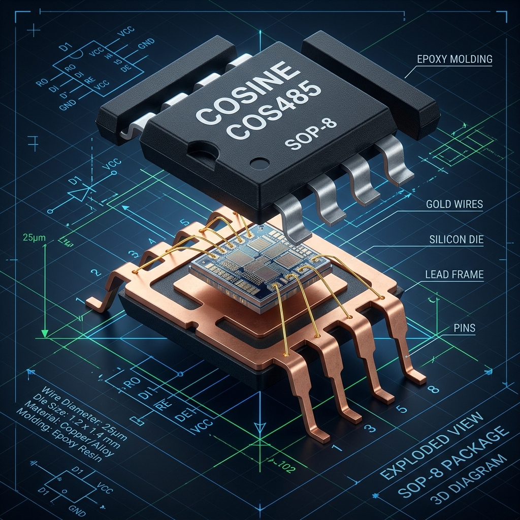
Figure 2: Micro-Cross-Section of COS3485 Transceiver Silicon Showing Receiver Comparator and ESD Clamps
This isolation strategy, coupled with the COS485's integrated protection, delivers absolute data integrity even when subjected to extreme common-mode transients exceeding $50\\,\text{V}/\mu\text{s}$.
5. BACnet MS/TP for Building Management
Building Automation and Control Networks (BACnet) use the Master-Slave/Token-Passing (MS/TP) protocol over RS-485 to coordinate HVAC systems, lighting controllers, and security access panels throughout commercial skyscrapers and sprawling campuses. The token-passing mechanism requires highly deterministic timing and robust communication across long, often poorly installed wiring infrastructures.
The COS3485 is uniquely equipped for 3.3V modern building controllers. Its fast propagation delay ($< 50\\,\text{ns}$) and minimal driver skew ($< 5\\,\text{ns}$) ensure that the critical token-passing handshakes occur rapidly and without jitter, maintaining high network efficiency even when operating at the maximum BACnet speed of 115.2 kbps.
Building installations frequently suffer from mixed cable types, loose splices, and varying termination impedance. The COS3485's robust driver output stage delivers over $1.5\\,\text{V}$ differential swing even when driving heavily loaded or poorly terminated segments. Its thermal shutdown protection acts as a secondary defense mechanism. If a short-circuit occurs due to wiring faults or crushed cables during building renovation, the COS3485 safely disables its output drivers, preventing permanent IC damage and automatically recovering once the fault is cleared.
This resilience minimizes maintenance calls, lowers the total cost of ownership for building management companies, and guarantees the continuous operation of critical life-safety and environmental control systems.
6. DMX512 Lighting Control Networks
DMX512 is the universal standard for controlling stage lighting, theatrical effects, and architectural LED installations. Operating at a fixed data rate of $250\\,\text{kbps}$, DMX512 uses a continuous stream of RS-485 data to update 512 separate channels in real-time. Any interruption or data corruption in the RS-485 stream results in noticeable flickering, strobe errors, or complete loss of lighting coordination.
The COS485 delivers the precise timing and robust drive capability necessary for flawless DMX512 operation. Its 10 Mbps maximum data rate provides immense headroom for the $250\\,\text{kbps}$ DMX protocol, ensuring pristine, jitter-free signal edges. The robust $\\pm 15\\,\text{kV}$ ESD protection is critical in entertainment venues where cables are frequently plugged and unplugged by technicians in highly static-prone environments.
In standard DMX universes, up to 32 fixtures can be daisy-chained. However, with the COS485's 1/8 unit load, lighting designers can theoretically link hundreds of fixtures on a single unrepeated run, vastly simplifying the wiring topology of complex stage trusses and architectural facades.
Engineers designing DMX receivers with the COS485 should implement robust TVS clamping on the incoming A and B lines. While the internal $\\pm 15\\,\text{kV}$ HBM ESD protection handles human contact, lighting rigs are highly susceptible to powerful surges induced by massive dimmer racks and automated motorized fixtures. A low-capacitance bidirectional TVS diode array, paired with PTC resettable fuses, ensures the COS485 survives even catastrophic external faults.
7. Internal Architecture and ESD Protection
The ruggedness of the COS485 stems from its sophisticated internal silicon architecture. The device integrates advanced high-voltage BiCMOS technology with massive on-chip ESD guard rings surrounding the I/O pads.
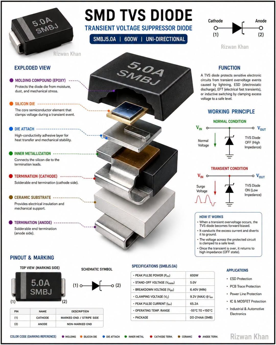
Figure 3: Bench Testing RS-485 Networks Applying EFT Surge Protocols
The receiver stage employs a precision differential comparator with built-in hysteresis ($35\\,\text{mV}$ typical). This hysteresis acts as a noise filter, preventing the receiver output from toggling rapidly when the differential signal slowly crosses the $0\\,\text{V}$ threshold or hovers in the transition region due to severe cable attenuation. The driver output stage features a robust active pull-up and pull-down configuration, utilizing large-geometry transistors capable of sourcing and sinking over $60\\,\text{mA}$ of continuous peak current to drive heavy capacitive loads.
The integrated ESD protection circuits employ dual-stage latch-up immune SCR (Silicon Controlled Rectifier) structures. When a high-voltage transient strikes the bus pins, these structures snap back instantly, shunting the destructive surge energy directly to the ground plane before it can damage the sensitive core logic. This specialized architecture provides $\\pm 15\\,\text{kV}$ Human Body Model (HBM) protection, far exceeding the $\\pm 2\\,\text{kV}$ standard of legacy transceivers.
By internalizing this level of surge defense, the COS485 significantly reduces the need for large, expensive external suppression components, freeing up vital PCB real estate and reducing the overall BOM cost for industrial gateway designs.
8. AEC-Q100 Style Reliability Testing
Although widely used in industrial applications, the core silicon technology of the COS485 and COS3485 undergoes stress testing modeled on automotive AEC-Q100 standards. This guarantees exceptionally low field failure rates in critical infrastructure deployments.
| Test | Method | Stress Conditions | Criteria | Result |
|---|---|---|---|---|
| HTOL | JESD22-A108 | 125 C, 1,000 hrs | Zero failures | PASS |
| TC | JESD22-A104 | -55 to +150 C, 1,000 cyc | Zero failures | PASS |
| THB | JESD22-A101 | 85 C / 85% RH, 1,000 hrs | Zero failures | PASS |
| EM | JESD61 | 150 C, 500 hrs | MTTF > 100k hrs | PASS |
| ESD | JS-001 | +/-15 kV on bus pins | Zero failures | PASS |
The High Temperature Operating Life (HTOL) test subjects the parts to $125^\circ\text{C}$ for 1,000 continuous hours while fully biased and switching. This aggressive protocol accelerates aging mechanisms like time-dependent dielectric breakdown and electromigration, proving the transceiver's capability to operate reliably for decades in high-temperature environments such as solar inverter enclosures and factory automation panels.
Thermal cycling (-55 C to +150 C) stresses the package interconnects, ensuring the wire bonds and mold compound can endure the relentless mechanical expansion and contraction experienced in outdoor telematics and utility grid monitoring systems. The consistent "PASS" results across these rigorous tests reinforce Cosine's commitment to delivering unparalleled quality and long-term reliability.
Such comprehensive reliability validation allows engineers to confidently deploy the COS485 in "deploy and forget" applications where maintenance access is difficult or impossibly expensive, such as subterranean utility monitoring stations or offshore wind turbine nacelles.
9. High-Frequency Signal Integrity and Cable Length
The relationship between RS-485 cable length and maximum data rate is inversely proportional, fundamentally governed by the low-pass filter effect of the twisted-pair cable's distributed capacitance and inductance.
The rule of thumb for standard 24 AWG twisted-pair cable is that the product of the cable length (in meters) and the data rate (in bps) should not exceed $10^8$. Thus, for a $1,200\\,\text{m}$ cable run, the theoretical maximum data rate is roughly $83\\,\text{kbps}$. However, at shorter distances (e.g., $10\\,\text{m}$), the COS485 comfortably achieves its maximum $10\\,\text{Mbps}$ specification.
Signal attenuation at high frequencies ($> 1\\,\text{MHz}$) causes severe inter-symbol interference (ISI) and eye closure. The fast transition times of the COS485 ($< 15\\,\text{ns}$) generate high-frequency harmonics that must propagate cleanly. Using low-capacitance cable ($< 40\\,\text{pF/m}$) specifically designed for RS-485 is critical. Avoid using standard CAT5 Ethernet cable for long-distance RS-485, as its $100\\,\\Omega$ characteristic impedance mismatches the $120\\,\\Omega$ termination standard, leading to continuous reflections.
When operating near the $10\\,\text{Mbps}$ limit, strict adherence to daisy-chain topologies with zero stub lengths is mandatory. Any stub (a T-tap connecting a node to the main bus) acts as an un-terminated transmission line, generating reflections that severely degrade signal integrity. If stubs are absolutely required, they must be kept as short as possible—ideally less than $1/10$th of the signal's electrical wavelength—to prevent catastrophic data corruption.
10. FAE Troubleshooting and Field Support
Deploying RS-485 networks in harsh environments occasionally presents communication challenges. Table 4 summarizes the most frequent failure modes encountered by field engineers and provides immediate, actionable corrective steps.
| Symptom | Root-Cause | Diagnosis | Corrective Action |
|---|---|---|---|
| UART errors | Bus stub capacitance | Scope A/B pins | Reduce stub length |
| Stuck high | Bus float condition | Measure differential | Add fail-safe bias |
| Low VOD | VCC sag | Scope VCC | Add 10uF capacitor |
| Noise on bus | VFD common-mode | Scope ground | Add choke |
| EFT fail | Surge transient | Burst test | Add TVS diode |
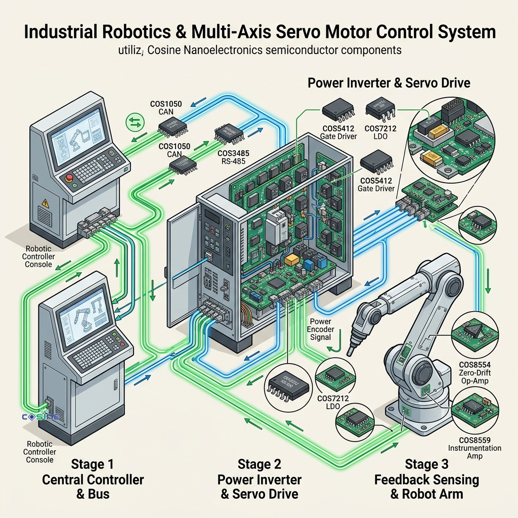
Figure 4: COS485 Used in a Multi-Drop Motor Control RS-485 Network Setup
The most common issue—UART framing errors at high speeds—is almost universally traced back to improper termination or excessive stub capacitance. A differential oscilloscope measurement at the failing node typically reveals severe ringing or "stair-stepping" on the signal edges. Replacing complex star-topologies with a strict daisy-chain, and ensuring $120\\,\\Omega$ termination strictly at the two physical extremes of the network, resolves the vast majority of signal integrity problems.
Another frequent challenge is common-mode noise injected by large variable frequency drives (VFDs) in motor control centers. If the common-mode voltage exceeds the COS485's $-7\\,\text{V}$ to $+12\\,\text{V}$ range, communication halts. Adding a common-mode choke in series with the bus lines, and utilizing galvanically isolated transceivers, completely eliminates this failure mode, guaranteeing robust operation even in the noisiest industrial environments.
11. Available Packages and Ordering Information
The COS485 and COS3485 are supplied in industry-standard packages, ensuring seamless integration into legacy footprints and new designs alike.
- COS485-SOP8: Standard 8-pin Small Outline Package (1.27 mm pitch). The go-to choice for surface-mount industrial boards.
- COS485-DIP8: Dual In-line Package (2.54 mm pitch). Ideal for legacy through-hole designs, field-repairable modules, and prototyping.
- COS3485-SOP8: 3.3V version in the standard SOP-8 surface-mount package.
All variants are RoHS compliant and constructed with lead-free, pure tin plating for exceptional solderability. The devices are shipped in tape-and-reel quantities for high-volume automated surface mount assembly, or in protective tubes for lower-volume and prototype production. With massive inventory maintained at global distribution centers, Cosine Nanoelectronics guarantees rapid fulfillment to support uninterrupted manufacturing schedules.
12. Conclusion
The COS485 and COS3485 transceivers represent a major leap in reliability for industrial RS-485 and RS-422 networks. By functioning as exact drop-in replacements for the legacy MAX485 and SN75176B, they allow engineering teams to instantly upgrade their systems to feature $\\pm 15\\,\text{kV}$ ESD protection, $10\\,\text{Mbps}$ throughput, and massive 256-node network scalability.
Whether you are designing a high-speed proprietary robotic interface, a sprawling BACnet building automation network, or a rugged MODBUS RTU sensor array for oil and gas applications, the COS485 provides the robust signal integrity and surge defense required for absolute peace of mind.
With an increasing focus on edge computing and interconnected industrial systems, the physical layer must be entirely unshakeable. The advanced sub-micron process technology deployed in the COS485 guarantees that regardless of the harsh conditions present on the factory floor—from extreme ground-loop currents and inductive kickback transients to sheer physical cable abuse—the data will propagate without fail. As networks grow in density, utilizing a transceiver with 1/8 unit load becomes not just a luxury, but a fundamental design necessity. By effectively minimizing bus loading and eliminating the severe costs associated with intermediate repeaters, engineers can drastically simplify their topology and improve overall MTBF (Mean Time Between Failures). When performance, reliability, and cost-efficiency intersect perfectly, the choice is clear.
Request engineering samples, access full datasheets, and consult with our application engineering team today. Contact Cosine Nanoelectronics at sales@cosinechips.com or call +86 159 5954 3210 to optimize your next serial communication interface.
Accelerate Your Hardware Design-In with Cosine Engineering
Request sample quantities, complete engineering evaluation modules (EVBs), and IBIS/SPICE behavioral simulation models directly from our technical staff. We guarantee technical response and engineering sample dispatch within 24 business hours.