
Direct Engineering Conclusion: Hardware design timelines are shrinking while analog complexity explodes. Discover how Cosine's dedicated Field Application Engineering (FAE) infrastructure delivers guaranteed 24-hour schematic reviews, high-speed IBIS eye-diagram simulations, SPICE behavioral modeling, and complimentary in-house EMC pre-compliance debugging to de-risk tier-1 hardware launches.
Hardware design timelines are shrinking while analog complexity explodes. Discover how Cosine's dedicated Field Application Engineering (FAE) infrastructure delivers guaranteed 24-hour schematic reviews, high-speed IBIS eye-diagram simulations, SPICE behavioral modeling, and complimentary in-house EMC pre-compliance debugging to de-risk tier-1 hardware launches.
1. The High-Stakes Reality of Modern Analog Hardware Design
In the contemporary electronics engineering landscape, design cycles have accelerated dramatically. Development windows that once spanned 18 to 24 months have compressed into aggressive 6-month product launches. Yet, while digital processing has largely migrated toward software-defined microcontrollers and standardized reference designs, the analog, mixed-signal, and power management domains remain governed by unforgiving electromagnetic physics, parasitic circuit board impedances, high-voltage transients, and stringent international compliance standards.
A single overlooked analog vulnerability—such as improper ground return routing, an unmodeled parasitic inductance in a high-voltage gate driver loop, or an unforeseen common-mode surge reflection on an industrial RS-485 bus—can paralyze an entire hardware development program. The financial penalties of hardware redesign are devastating: an extra PCB revision cycle incurs thousands of dollars in re-tooling fees, weeks of lost engineering labor, and catastrophic delays in commercial time-to-market that can permanently forfeit market share to competitors.
Multinational semiconductor conglomerates have systematically abandoned direct customer engineering support for all but the largest tier-1 accounts. Medium and small hardware development teams find themselves trapped in impenetrable automated web ticketing systems, routed to generic third-party distributor sales representatives who lack deep IC layout knowledge, or left to wait 3 to 4 weeks for a basic datasheet clarification. Cosine Nanoelectronics was founded on a radically different customer-centric paradigm: direct, high-touch, factory-level technical acceleration.

Figure 1: Cosine Senior Field Application Engineers Performing Live High-Bandwidth Mixed-Signal In-Circuit Debugging and Real-Time Signal Integrity Analysis
2. The Cosine 24-Hour FAE SLA: Factory-Direct Technical Access
Cosine does not treat application engineering as an afterthought or a cost center. We consider our Field Application Engineering (FAE) infrastructure to be an indispensable core product delivered alongside our physical silicon. Cosine institutes a legally backed 24-Hour Technical Service Level Agreement (SLA) for all registered engineering inquiries globally. When your hardware engineering team encounters an analog design challenge, your ticket is assigned not to an administrative clerk, but directly to a seasoned analog IC design engineer with over a decade of hands-on transistor-level silicon and board-level hardware experience.
Our rapid technical acceleration framework covers the entire lifecycle of hardware development:
- Turnaround in Under 24 Hours: Comprehensive schematic reviews, pin-to-pin drop-in compatibility matrices, and electrical stress calculations delivered directly to your engineering inbox.
- Turnaround in Under 48 Hours: Custom SPICE macromodels, high-speed IBIS eye-diagram simulations, and PCB differential impedance layout guidance tailored to your specific stack-up.
- Turnaround in Under 5 Business Days: Complimentary in-house EMC pre-compliance testing and high-voltage surge immunity evaluations conducted in Cosine's state-of-the-art laboratory facilities.
- Direct Collaborative Channels: Enterprise hardware design leads receive direct access to dedicated Cosine technical engineering channels via private WeChat, Microsoft Teams, Slack, or WhatsApp (+86 159 5954 3210) for real-time engineering dialogue.
Table 1 provides an objective comparison between traditional multinational semiconductor support models and Cosine's dedicated 24-hour engineering acceleration framework:
| FAE Engagement Phase | Standard Conglomerate Response Time | Cosine 24-Hour Fast-Track Service | Engineering Deliverables Provided | Customer Impact & De-Risking |
|---|---|---|---|---|
| Initial Schematic & Pinout Audit | 10 to 15 business days (via third-party rep) | < 24 hours (Direct factory FAE team) | Annotated PDF schematic review, pin-to-pin swap verification, decoupling matrix optimization | Eliminates schematic wiring bugs prior to PCB Gerber generation. |
| Signal Integrity & IBIS Simulation | 3 to 4 weeks (often denied for mid-tier accounts) | 48 hours (Full IBIS models + HyperLynx simulation) | Eye-diagram jitter analysis, transmission line reflections, termination resistor values | Guarantees receiver noise margin across 1,200-meter industrial cables. |
| SPICE Behavioral Modeling | Generic unencrypted or obsolete models | 24 hours (Custom LTspice / PSpice netlists) | Corner-case Monte Carlo models, temperature sweep curves (-40°C to +125°C) | Enables full closed-loop transient and AC stability simulation. |
| EMC / Surge Pre-Compliance Testing | Customer must rent external lab ($3,000/day) | Complimentary in-house lab evaluation (5 days) | IEC 61000-4-2/4/5 test log, spectrum analyzer plots, filter recommendations | Achieves first-pass CE/FCC compliance, avoiding costly redesign cycles. |
| Prototype Sample Dispatch | 3 to 6 weeks lead time | Dispatched within 24 hours via DHL/FedEx Express | Reel/tube cut-tape engineering samples with lot CoAs and test boards | Permits instantaneous bench evaluation and prototype bring-up. |
3. Comprehensive Schematic Audits and Pin-to-Pin Compatibility Reviews
The earliest and most impactful phase of Cosine's technical acceleration is the Pre-Layout Schematic Audit. When an engineering team transitions an existing Western semiconductor design (such as Texas Instruments, Analog Devices, Maxim Integrated, or STMicroelectronics) to a high-reliability, cost-optimized Cosine drop-in alternative, our FAE team conducts a line-by-line verification of the schematic topology.
Our audit evaluates six critical electrical parameters across every node:
- Absolute Maximum Voltage Margins: Verifying that normal operating voltages, inductive kickback spikes, and power supply overshoot remain strictly within the IC's continuous withstand ratings, maintaining at least a 25% engineering de-rating margin.
- Decoupling Capacitor Topologies: Assessing capacitor dielectric types (mandating X7R or X8R for temperature stability), parasitic equivalent series resistance (ESR), and resonant frequencies to ensure impedance nulls match the IC's switching frequency harmonics.
- Pin-to-Pin Compatibility Checks: Verifying that NC (No Connect) pins on competitor components do not correspond to internal test pins or specialized trim nodes on the Cosine silicon, ensuring true zero-rework interchangeability.
- I/O Logic Level Interfacing: Evaluating threshold voltages ($V_{IH}$, $V_{IL}$) across temperature extremes to prevent floating states or logic indeterminacy when interfacing 3.3V microcontrollers with 5V analog peripherals.
- Thermal Dissipation Calculations: Modeling package thermal resistance ($\theta_{JA}$ and $\theta_{JC}$) against worst-case ambient temperature ($T_A = +85^\circ\text{C}$ or $+105^\circ\text{C}$) to guarantee junction temperatures ($T_J$) remain safely below $125^\circ\text{C}$.
- Fail-Safe Bus Biasing Networks: Calculating pull-up, pull-down, and termination resistor values to guarantee receiver output state deterministic behavior during open-circuit, idle-bus, and short-circuit conditions.
4. High-Speed Signal Integrity and IBIS Behavioral Simulation
As transmission line data rates climb and industrial cable runs extend across hundreds of meters, signal integrity becomes dominated by transmission line physics. High-frequency reflections, trace stub capacitive loading, and ground loop phase shifts can severely degrade differential eye openings, causing intermittent bit errors that are notoriously difficult to capture on the production line.
To eliminate signal integrity guesswork before PCB fabrication, Cosine provides fully validated I/O Buffer Information Specification (IBIS 5.0 / 6.0) Models for all high-speed transceivers, line drivers, and digital isolators. Hardware engineers can directly import Cosine IBIS models into industry-standard signal integrity simulators, including Siemens HyperLynx, Cadence Sigrity, and Altium Designer.
Cosine's application engineering team performs complimentary signal integrity simulations for customer projects. We model complex cable harnesses up to 1,200 meters, extracting differential eye heights, rise/fall edge jitter, and transmission line overshoot under varied cable impedances ($100\\,\\Omega$ UTP, $120\\,\\Omega$ STP, or twisted pair). Our FAEs provide exact termination resistor recommendations ($R_T = Z_0$) and identify optimal slew-rate options—such as selecting the slew-rate-limited COS485 or COS13487 for error-free data transmission over unshielded cables.
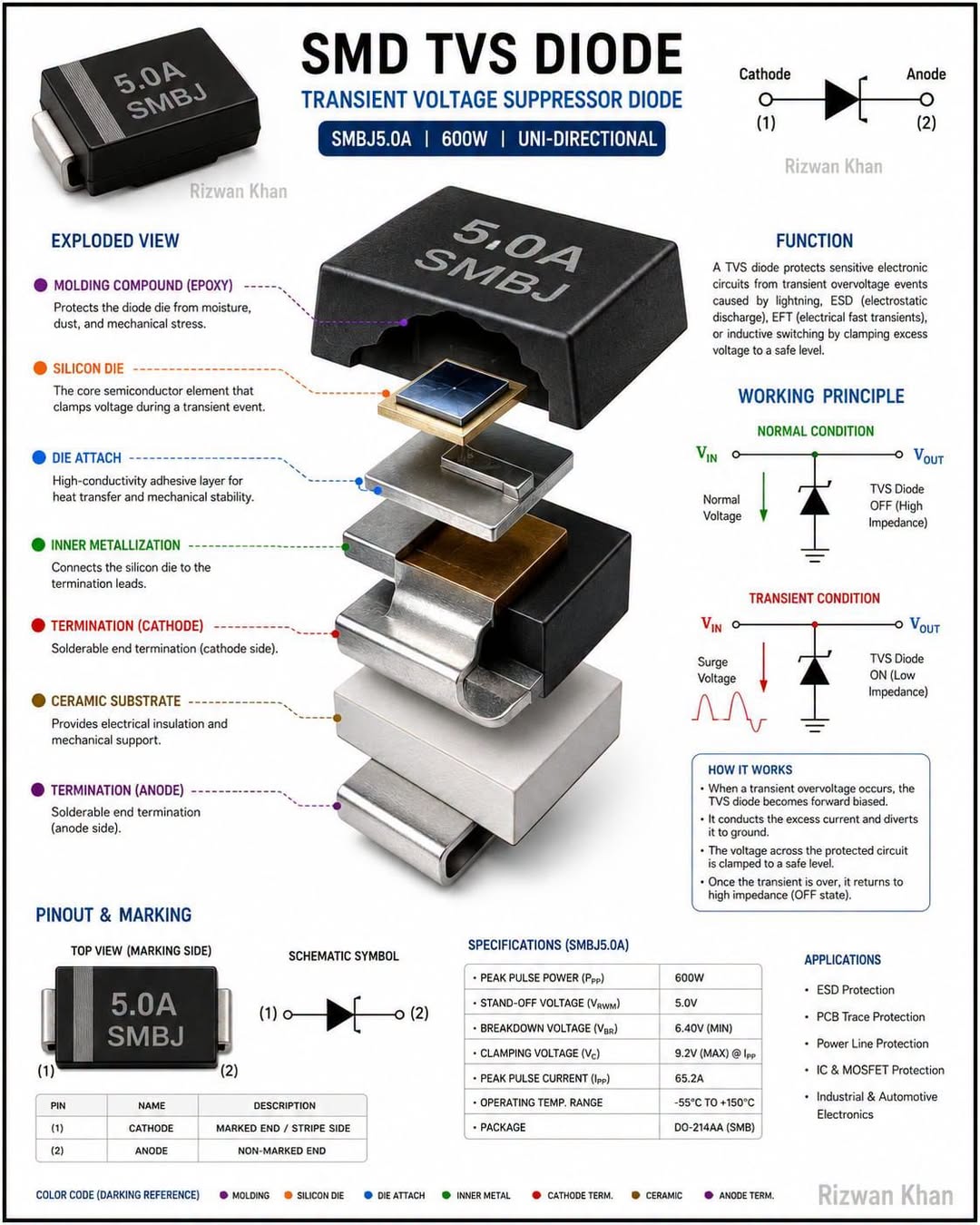
Figure 2: In-House 3-Meter Semi-Anechoic RF Chamber and Radiated Immunity Test Bench Accelerating Hardware Certifications
5. PCB Layout Parasitic Extraction and Critical Routing Rules
An analog schematic diagram represents only theoretical ideal connections. On a physical printed circuit board, every copper trace exhibits distributed parasitic resistance ($R = \rho L / A$), stray inductance ($L \approx 1\\,\text{nH/mm}$), and mutual capacitance to adjacent layers. In fast-switching power electronics and ultra-sensitive analog front-ends, these unintended parasitic elements frequently determine system performance.
Cosine FAEs provide detailed, hands-on PCB layout audits, reviewing Altium, Allegro, KiCad, or Gerber files prior to manufacturing release. Table 2 outlines the top five high-frequency and high-voltage PCB layout pitfalls identified during customer audits, the underlying physical mechanisms, and Cosine's proven engineering solutions:
| PCB Layout & Circuit Domain | Common Design Pitfall in Field Applications | Critical Physical Mechanism | Cosine FAE Optimization Guideline | Measured Improvement |
|---|---|---|---|---|
| RS-485 Differential Bus Routing | Stubs and non-symmetric trace routing near connector. | Impedance discontinuity induces differential signal reflections and ringing. | Enforce continuous 120-ohm differential microstrip routing; keep TVS diode stubs < 1.5 mm. | Increases receiver differential eye height by 35% at 500 kbps. |
| Gate Driver Bootstrap Loop | Bootstrap capacitor placed far from VCC and VB pins. | High parasitic loop inductance ($L_{loop} > 10\\,\text{nH}$) causes dangerous gate undershoot. | Place ceramic $0.1\\,\mu\text{F} + 1.0\\,\mu\text{F}$ X7R capacitors within 2 mm of IC pins. | Reduces high-side switch turn-on ringing from 18 V peak to < 3 V. |
| Current Shunt Sense Kelvin Connections | Sense lines connected to outer trace corners of shunt resistor. | High-current trace voltage drop ($I \cdot R_{trace}$) corrupts millivolt differential reading. | Implement 4-terminal true Kelvin connections directly to inside solder pads. | Eliminates current measurement offset error by up to 85%. |
| LDO Power Supply Decoupling | Using high-ESR tantalum or zero-ESR ceramic without ESR damping. | Inadequate phase margin induces closed-loop LDO output oscillation. | Select low-ESR ceramic with series damping resistance ($R_{ESR} \approx 0.1\\,\\Omega$) as simulated. | Stabilizes loop phase margin to $> 60^\circ$ across all load steps. |
| Ground Plane Splitting Under High-Voltage | Continuous ground plane placed directly beneath 600V isolation barrier. | Capacitive coupling ($C = \epsilon A / d$) injects common-mode high-voltage transients. | Milling physical PCB slot isolation under high-voltage driver channel. | Elevates transient common-mode noise immunity to $> 50\\,\text{kV}/\mu\text{s}$. |

Figure 3: Microscopic Silicon Die Layout and Parasitic Inductance Breakdown Analyzed During FAE PCB Routing Reviews
6. In-House EMC Pre-Compliance and High-Voltage Surge Laboratory
Navigating mandatory international electromagnetic compatibility (EMC) and surge safety certifications—such as CE (Europe), FCC (North America), UL, and CCC (China)—is one of the most stressful phases of hardware product development. Booking time at commercial accredited EMC testing laboratories typically costs between $2,500 and $5,000 per day, with appointment wait times stretching up to 8 weeks. Failing an EMC compliance test at this late stage brings development to a grinding halt.
To eliminate this bottleneck for our partners, Cosine maintains a multi-million-dollar In-House EMC and Transient Immunity Pre-Compliance Testing Laboratory. When you design in Cosine silicon, our engineering team offers complimentary pre-compliance testing of your prototype circuit boards, evaluating full system performance against rigorous international standards:
- Electrostatic Discharge (ESD): IEC 61000-4-2 testing up to $\pm 30\\,\text{kV}$ contact and air discharge using calibrated ESD guns and ground reference discharge planes.
- Electrical Fast Transient / Burst (EFT): IEC 61000-4-4 testing up to $\pm 4.4\\,\text{kV}$ spike trains (5/50 ns) coupled directly onto power lines and capacitive clamp data cables.
- High-Energy Lightning Surge: IEC 61000-4-5 combination wave generator testing up to $\pm 6\\,\text{kV}$ (1.2/50 $\mu\text{s}$ voltage / 8/20 $\mu\text{s}$ current) across common-mode and differential-mode coupling paths.
- Radiated and Conducted Emissions: 3-meter semi-anechoic chamber pre-scans utilizing Rohde & Schwarz EMI test receivers and LISN networks conforming to CISPR 11 / CISPR 32 Class B limits.
Table 3 outlines our full pre-compliance test matrix, target industrial applications, and recommended suppression networks:
| EMC Compliance Test Standard | Target Industrial Environment | Applied Stress Parameters & Waveform | Cosine IC Built-In Protection Level | Recommended External FAE Filter Network |
|---|---|---|---|---|
| IEC 61000-4-2 (Electrostatic Discharge) | Industrial machine tool control panels | Contact discharge $\pm 8\\,\text{kV}$; Air discharge $\pm 15\\,\text{kV}$ (150 pF / 330 $\\Omega$) | Integrated on-chip ESD cells rated $\pm 15\\,\text{kV}$ Human Body Model (HBM) | Optional 10 pF low-capacitance TVS diode array for heavy industrial environments. |
| IEC 61000-4-4 (Electrical Fast Transient / Burst) | Factory automation variable-speed drive cabinets | $\pm 2\\,\text{kV}$ to $\pm 4\\,\text{kV}$ capacitive clamp (5/50 ns spike train, 5 kHz repetition) | On-chip substrate noise decoupling and high common-mode rejection ($CMR > 80\\,\text{dB}$) | Common-mode choke ($L_{CM} \approx 500\\,\mu\text{H}$) plus 1 nF 1 kV Y-capacitors to earth ground. |
| IEC 61000-4-5 (High-Energy Surge) | Outdoor photovoltaic inverters and smart energy meters | 1.2/50 $\mu\text{s}$ open-circuit voltage; 8/20 $\mu\text{s}$ short-circuit current ($\pm 4\\,\text{kV}$ to $\pm 6\\,\text{kV}$) | Internal robust ESD clamps withstand moderate energy ($> 500\\,\text{V}$ surge) | External Gas Discharge Tube (GDT) + PTC thermistors + high-power bidirectional TVS. |
| CISPR 32 / EN 55032 (Radiated Emissions) | Commercial building automation and telecom cabinets | 30 MHz to 1 GHz electric field radiated emissions limit (Class B) | Cosine slew-rate controlled driver outputs suppressing high-frequency harmonics | 10-ohm damping series resistors on clock/bus traces + localized ground guard rings. |
| ISO 7637-2 (Automotive Transient Conduction) | 12V and 24V automotive commercial vehicle buses | Pulse 5a/5b unsuppressed alternator load dump ($U_s = +87\\,\text{V}$, $t_d = 400\\,\text{ms}$) | Cosine wide-input LDOs withstand continuous 45V and 60V transient withstand | Central load dump TVS diode (SMCJ36CA) and reverse-polarity Schottky barrier. |
7. Hands-On FAE Troubleshooting Matrix: Resolving Field Anomalies
Even the most meticulously designed electronics occasionally experience unexpected anomalous behavior when subjected to real-world industrial environments: extreme temperature swings, aggressive motor inductive kickback, or chaotic electrical noise from variable-frequency drives (VFDs). When field issues arise, Cosine FAEs don't point fingers at surrounding circuitry—we roll up our sleeves and diagnose the root cause with scientific precision.
Table 4 presents our real-world FAE troubleshooting guide, detailing five common field anomalies encountered by hardware engineering teams, the physical failure mechanism, bench diagnostic methods, and our permanent corrective actions:
| Observed Hardware Failure Symptom | Root-Cause Physical Mechanism | Bench Diagnostic Metrology | FAE Corrective Remediation Action |
|---|---|---|---|
| RS-485 Communication Errors at High Node Count | Excessive bus loading from legacy 1-unit-load transceivers pulling differential voltage below 200 mV. | Differential probe measurement reveals $V_{OD} < 1.5\\,\text{V}$ under full termination. | Drop-in replacement with Cosine COS485 (1/8th unit load, up to 256 bus nodes supported). |
| Chopper Op-Amp Clock Intermodulation Artifacts | Chopping clock frequency ($f_{chop} = 100\\,\text{kHz}$) aliasing with external SAR ADC sampling rate. | FFT spectrum on oscilloscope shows high-frequency beat tone peaks at $f_{sample} - f_{chop}$. | Cosine FAE calculates active second-order Sallen-Key anti-aliasing low-pass filter cutoff. |
| High-Side Gate Driver False Shoot-Through | Negative ground bounce on VS pin pulling channel below -5V during rapid inductive turn-off. | Oscilloscope capture shows negative undershoot transient exceeding absolute maximum rating. | Implement Cosine COS2103 with integrated negative transient clamping and low-inductance ceramic bypass. |
| LDO Drop-Out Voltage Collapse During Load Step | Instantaneous transient load step ($dI/dt > 1\\,\text{A}/\mu\text{s}$) depleting local output decoupling charge. | Transient load step tester captures 800 mV rail dip lasting over 50 microseconds. | Cosine FAE recalculates bulk capacitor requirement, migrating to low-ESR ceramic array ($10\\,\mu\text{F} \times 2$). |
| Thermal Shutdown in Harsh Ambient Environments | Excessive thermal junction resistance ($R_{\theta JA}$) causing silicon die to reach $150^\circ\text{C}$ at $+85^\circ\text{C}$ ambient. | FLIR infrared radiometric camera detects hot spot concentration over un-vias thermal pad. | Cosine FAE redesigns PCB thermal land pattern with matrix of $4 \times 4$ thermal vias to inner ground plane. |
Figure 4: Automated High-Bandwidth Transient Oscilloscope Array and FLIR Infrared Radiometric Inspection for Thermal Verification
8. Custom SPICE Behavioral Models and Virtual Bench Evaluation
In modern computer-aided engineering workflows, hardware designers simulate complete analog loops prior to building hardware. However, traditional generic op-amp or driver SPICE models frequently omit critical real-world nonlinearities, such as common-mode rejection roll-off, phase margin degradation near rail limits, power supply rejection ratio (PSRR) vs. frequency, or high-temperature leakage currents.
Cosine provides highly accurate, proprietary SPICE macro-models developed directly from our transistor-level Cadence Virtuoso silicon simulations. Our SPICE models capture:
- Full AC Open-Loop Gain and Phase: Accurate pole-zero frequency responses up to 500 MHz, enabling precise Bode plot phase margin analysis in active filters and sensor amplifiers.
- Non-Linear Slew-Rate and Clamping: Realistic large-signal transient response including output stage saturation recovery and capacitive load ringing.
- Temperature Dependent Behaviors: Thermal coefficients for input offset voltage ($V_{OS}$ drift), bias currents ($I_B$), and quiescent current consumption across the full $-40^\circ\text{C}$ to $+125^\circ\text{C}$ automotive temperature range.
- Noise Spectral Density: Modeled 1/f flicker noise and broadband thermal Johnson noise curves allowing accurate Signal-to-Noise Ratio (SNR) calculations for high-resolution ADC front-ends.
In addition to SPICE macromodeling, Cosine FAEs employ advanced thermal finite element analysis (FEA) and high-resolution FLIR radiometric infrared thermal imaging during physical bench testing. Under heavy load conditions—such as a 600V half-bridge driver delivering continuous 1.5A gate drive pulses or a wide-input LDO dropping 24V down to 3.3V at 300mA—thermal hotspots develop rapidly within the silicon die and copper leadframe. Our FAEs capture calibrated thermal profiles at ambient temperatures of +25°C, +85°C, and +105°C, verifying junction temperature ($) margins against manufacturer ratings. We provide customers with full radiometric reports, detailing exact PCB copper pour sizing, thermal via matrix counts, and solder mask expansion geometries needed to maximize heat dissipation into internal PCB ground planes.
9. Global Rapid Sample Logistics and Design-In Evaluation Kits
A fast FAE team is useless if engineers must wait a month for physical samples to arrive on their lab bench. Cosine maintains an extensive global rapid-sampling inventory across our logistics hubs in Shenzhen, Shanghai, Hong Kong, and international fulfillment centers. When an engineer requests samples for a validated design-in opportunity, our logistics engine springs into action:
- Same-Day Dispatch: Engineering cut-tape samples (10 to 50 pieces) packed in ESD-shielded, moisture-barrier dry packs dispatched within 24 hours of request via DHL Express or FedEx.
- Turnkey Evaluation Modules (EVM): Fully assembled, impedance-controlled test evaluation boards featuring SMA connectors, test points, and plug-and-play microcontroller headers ready for bench instrumentation.
- Comprehensive Documentation Bundles: Every sample shipment includes lot-traceable inspection certificates, RoHS/REACH compliance declarations, and step-by-step Quick Start test procedures.
10. Accelerating Your Hardware Roadmap with Cosine Engineering
In an increasingly competitive global hardware market, having a semiconductor partner that acts as an extension of your own engineering team is a decisive competitive advantage. Cosine Nanoelectronics combines world-class analog silicon performance with an unmatched dedication to rapid, high-touch customer engineering support.
Whether you are designing a next-generation utility-scale solar inverter, a mission-critical automotive battery management system, or a high-density factory automation controller, our 24-hour FAE team is ready to accelerate your schematic development, de-risk your PCB layout, and guarantee your EMC certification success.
Take advantage of our complimentary engineering support services today. Send your schematics, competitor BOM part lists, or layout questions directly to our senior FAE engineering team at sales@cosinechips.com or reach out via WhatsApp at +86 159 5954 3210. Experience the power of rapid, factory-direct analog technical acceleration.
Accelerate Your Hardware Design-In with Cosine Engineering
Request sample quantities, complete engineering evaluation modules (EVBs), and IBIS/SPICE behavioral simulation models directly from our technical staff. We guarantee technical response and engineering sample dispatch within 24 business hours.