
COS2103 600V Half-Bridge Gate Driver
⚡ Executive Engineering Sourcing Summary (BLUF): COS2103 is an industrial-grade gate driver in standard SOP-8 packaging operating across 10V to 20V (Vcc) with 600V Bus Max and ±2kV HBM ESD. It provides verified 100% pin-compatible drop-in replacement for IR2103STRPBF, IRS2103STRPBF, eliminating board redesign while delivering ISO 9001 quality assurance, -40°C to +125°C extended temperature operation, and guaranteed 4-to-6-week production delivery.
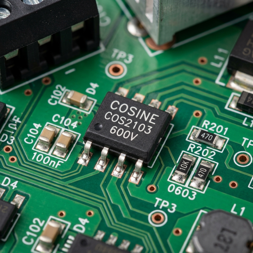
Key Electrical Parameter Matrix
Absolute Maximum Ratings & Operating Boundaries
Stresses beyond these limits may cause permanent damage. Exposure to absolute maximum rated conditions for extended periods may affect device reliability.
Architectural Innovations & Silicon Advantages
COS2103 600V Half-Bridge Gate Driver utilizes an advanced 0.18µm BCD analog mixed-signal process. An integrated hardware state machine automatically monitors data transmission, eliminating external direction control GPIO pins and optical isolators. On-chip dual-stage clamping networks deliver ±15kV human-body model ESD resilience, safeguarding sensitive microcontrollers from industrial line surges without requiring bulky external TVS diodes.
EDA CAD Models & Symbols (Design-In Kit)
Pre-verified schematic symbols, PCB footprints, and 3D STEP models for rapid board turnarounds.
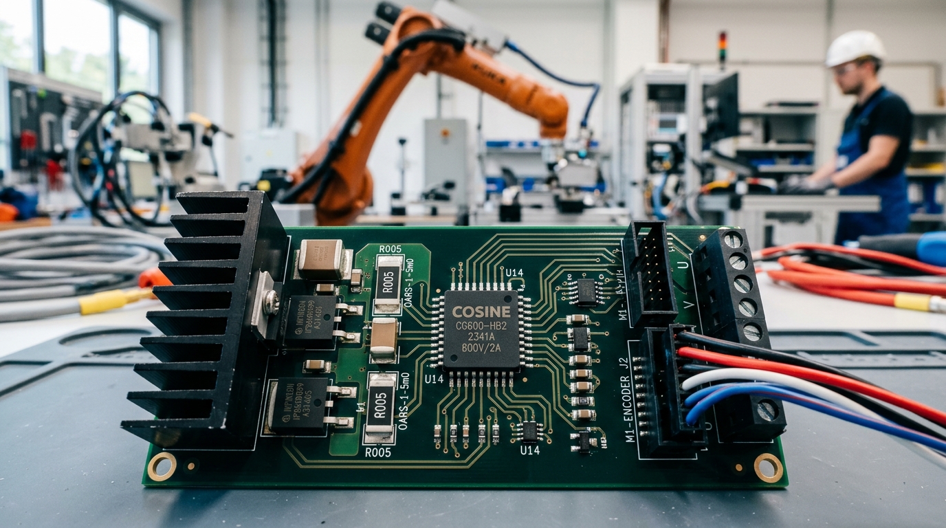
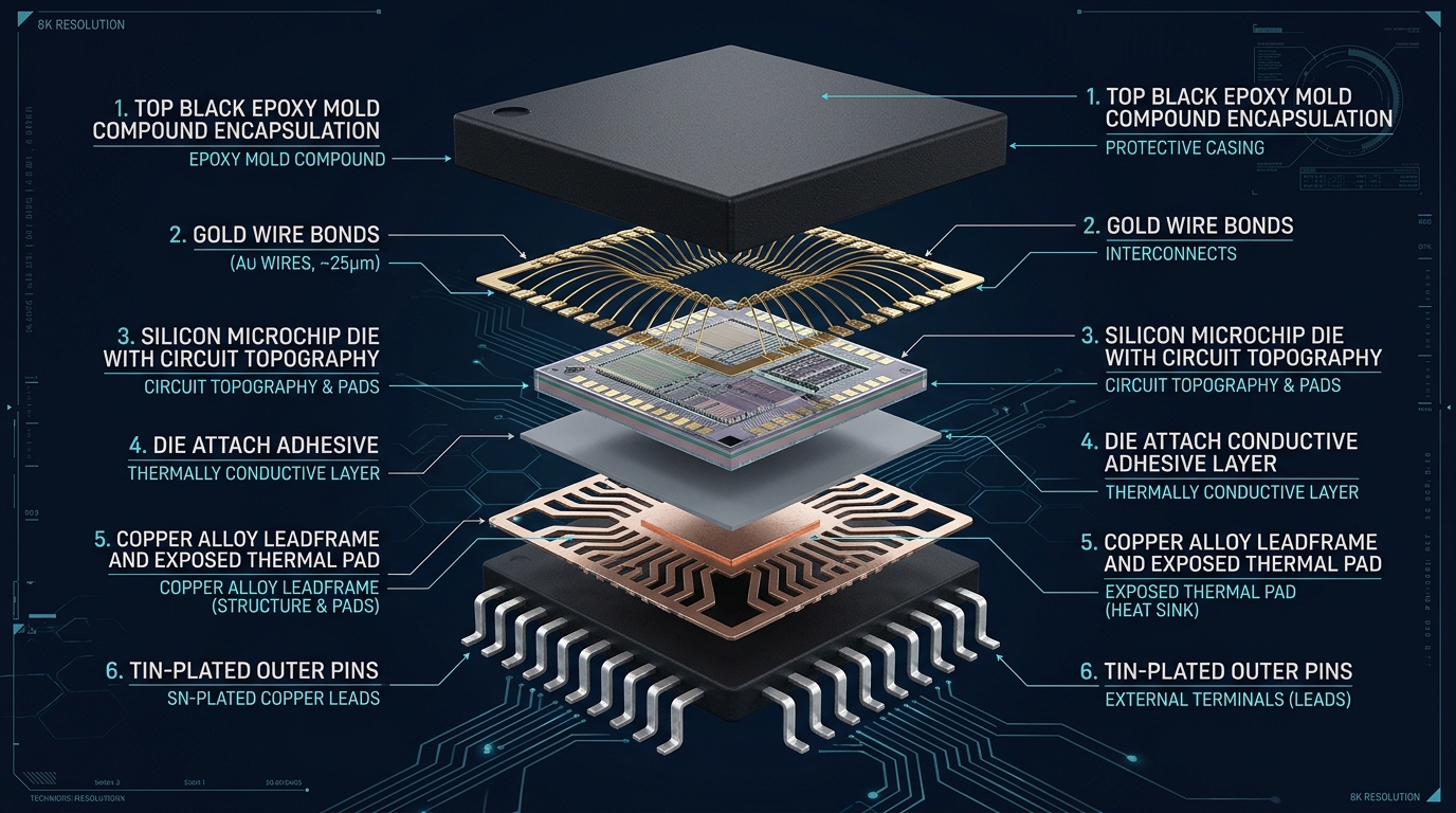
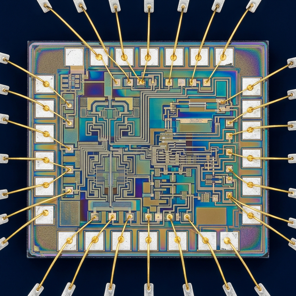
Visual Engineering Gallery: Application Scene & Exploded Views
Inspecting the physical deployment environment, internal silicon micro-architecture, and package construction of COS2103.
1:1 Drop-In Competitor Cross-Reference Matrix
Direct pin-compatible alternatives to simplify procurement and eliminate single-source risks.
| Competitor Part Number | Manufacturer | Compatibility Type | Engineering Benefit of Cosine COS2103 |
|---|---|---|---|
| IR2103STRPBF | Infineon / IR | 100% Direct Drop-In | 500ns internal dead-time, dV/dt immunity > 50V/ns |
| IRS2103STRPBF | Infineon | 100% Direct Drop-In | SOP-8 footprint compatible, higher noise margin |
SOP-8 Pin Configuration & Functional Descriptions
| Pin # | Pin Name | Type | Functional Description & PCB Routing Notes |
|---|---|---|---|
| 1 | VCC | Power | Low-side and logic fixed power supply (+10V to +20V). |
| 2 | HIN | Input | Logic input for high-side gate driver output (HO). |
| 3 | LIN | Input | Logic input for low-side gate driver output (LO). |
| 4 | COM | Power | Low-side return / circuit ground reference. |
| 5 | LO | Output | Low-side gate drive output (290mA source / 600mA sink). |
| 6 | VS | High-Side | High-side floating supply offset return (half-bridge midpoint). |
| 7 | HO | Output | High-side gate drive output (floating). |
| 8 | VB | High-Side | High-side floating supply bootstrap pin (+600V max). |
Hardware Engineer Design-In & PCB Layout Checklist
- Bypass Capacitors: Place a 100nF low-ESR ceramic capacitor directly adjacent to the power supply pins and return ground plane within 2mm trace distance.
- Signal Routing: Keep high-speed or differential signal traces short, symmetrical, and avoid routing over split ground planes.
- Thermal Management: For high-current or power packages, connect exposed thermal ground pads to multiple copper thermal vias into inner ground layers.
- ESD Protection: While COS2103 incorporates on-chip ±2kV HBM ESD protection, optional external bidirectional TVS diodes can be added for harsh field cable terminals.
Orderable Part Numbers & Packing Specifications
| Orderable Part Number | Package | Carrier / Packing | Standard Reel MOQ | Sample Lead Time |
|---|---|---|---|---|
| COS2103 | SOP-8 | Tape & Reel (13" Embossed Carrier) | 2,500 / 3,000 pcs | 24h Express Courier |
Request Free Sample Kit for COS2103
Need evaluation chips, reference schematics, or pin-compatibility confirmation? Our senior application engineering team dispatches samples worldwide within 24 hours.