
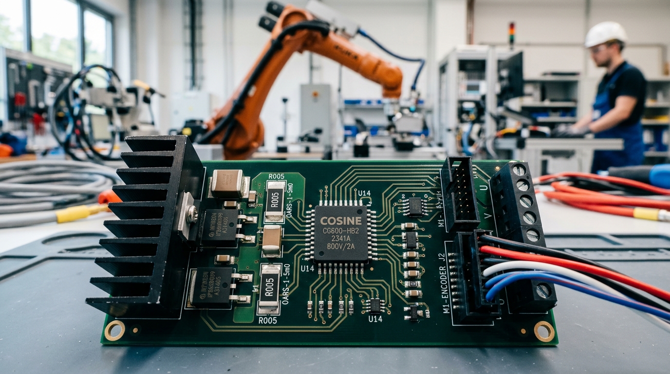
Key Power Management Metric: Driving high-voltage MOSFETs and IGBTs in bridge topologies requires robust isolation against high dV/dt switching transients. The Cosine COS2103 provides a 600V floating high-side channel with CMTI > 50 V/ns, built-in 500ns deadtime, and propagation delay matching within 10ns, directly replacing IR2103 and IRS21064 while preventing destructive cross-conduction shoot-through.
1. Gate Driver Technical Benchmark
| Parameter | Cosine COS2103 | Industry IR2103 | Cosine COS2101 | Cosine COS4427 (Low-Side) |
|---|---|---|---|---|
| High-Side Floating Voltage (VB) | 600 V Max | 600 V Max | 600 V Max | 25 V (Low-Side Only) |
| Peak Drive Current (Source/Sink) | 290 mA / 600 mA | 200 mA / 350 mA | 2.0 A / 2.0 A | 1.5 A / 1.5 A Dual |
| Built-In Deadtime (DT) | 500 ns (Typ) | 520 ns (Typ) | None (Independent) | None |
| Propagation Delay Matching | < 10 ns | < 50 ns | < 10 ns | < 5 ns |
| dV/dt Transient Immunity (CMTI) | > 50 V/ns | > 25 V/ns | > 50 V/ns | N/A |
| Package Options | SOP-8, DIP-8 | SOIC-8, PDIP-8 | SOP-8 | SOP-8, MSOP-8, DFN |
2. Bootstrap Circuit Sizing Equations
The high-side floating gate drive voltage is refreshed during each low-side conduction period via an external bootstrap diode and capacitor. Proper sizing of the bootstrap capacitor \(C_{BOOT}\) ensures that the high-side gate charge \(Q_G\) is delivered without triggering Under-Voltage Lockout (UVLO):
For typical 15kHz to 50kHz industrial motor drives using 40A IGBTs, a 1µF to 2.2µF X7R ceramic capacitor paired with an ultra-fast recovery diode (such as ES1J with \(t_{rr} < 25 ext{ns}\)) is recommended.
Need Drop-In Evaluation Samples or Schematic Review?
Our senior FAE engineers provide 24-hour turnaround for PCB schematic checks, drop-in replacement pin audits, and express sample kits dispatch.