
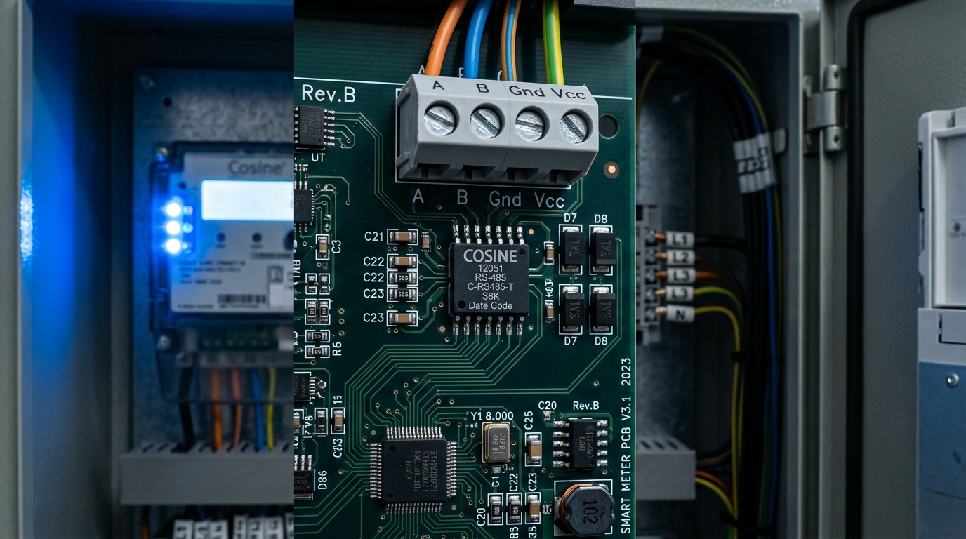
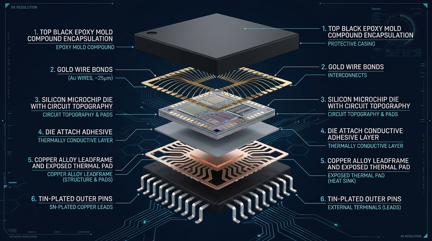
Key Sourcing Takeaway: In industrial automation, smart electricity meters, and automotive fieldbuses, transceiver reliability dictates system uptime. The Cosine COS485 and COS13487 transceivers exceed legacy industry standards (such as MAX485, SN75176B, and MAX13487) by integrating 1/8 Unit Load (256 nodes), ±15kV HBM ESD bus protection, and true failsafe receiver architectures that ensure known logic states during open, shorted, or idle bus conditions.
1. Parametric Comparison Matrix
Below is the verified engineering test matrix comparing Cosine's flagship transceivers against mainstream global semiconductor counterparts. All values are tested across the -40°C to +125°C extended industrial temperature span.
| Parameter | Cosine COS485 | Standard MAX485 | Cosine COS13487 | Cosine COS1051 (CAN) |
|---|---|---|---|---|
| Max Data Rate | 10 Mbps | 2.5 Mbps to 5 Mbps | 500 kbps (Slew-Rate Ltd) | 1 Mbps (CAN-FD 5 Mbps) |
| Driver Enable (DE) Control | Standard MCU GPIO | Standard MCU GPIO | Automatic Direction State Machine | MCU TxD / Mode Pin |
| Bus Unit Load / Max Nodes | 1/8 UL (256 Nodes) | 1 UL (32 Nodes) | 1/8 UL (256 Nodes) | 110+ Nodes on Bus |
| Common-Mode Voltage Range | -7V to +12V | -7V to +12V | -7V to +12V | -12V to +12V |
| HBM ESD Bus Protection | ±15 kV HBM | ±2 kV to ±4 kV | ±15 kV HBM | ±8 kV Contact / ±15 kV Air |
| Quiescent Current (Icc) | 300 µA typ | 900 µA typ | 350 µA typ | 1.2 mA typ |
| Direct Drop-In Target | MAX485, SN75176B, ADM485 | Industry Baseline | MAX13487EESA, THVD1406 | TJA1051, MCP2551 |
2. Common-Mode Rejection & Surge Protection Architecture
Ground potential differences (GPD) across distributed industrial networks can easily reach ±7V or more, particularly during motor starting or lightning surge events. Cosine transceivers feature proprietary internal high-voltage ESD clamping diodes on both A and B bus terminals, paired with balanced differential input stages.
For automated direction control in smart meters, the COS13487 incorporates an internal edge-detecting state machine. When the MCU transmits a low bit via the DI pin, the driver actively drives the differential bus lines. When transmitting a high bit or idle state, the driver releases the bus within nanoseconds, allowing passive failsafe termination to pull the bus into a legitimate logic-high state. This completely eliminates optocoupler count and GPIO timing errors in isolated RS-485 nodes.
3. PCB Layout & Decoupling Recommendations
- Decoupling Capacitor: Place a 100nF low-ESR ceramic capacitor within 2mm of the VCC pin (Pin 8) and ground plane.
- Differential Trace Routing: Route bus lines A and B as a 120Ω differential pair with matched trace lengths (within ±0.5mm).
- Bus Termination: Place a 120Ω 1% metal film termination resistor at each end of the transmission line.
- Transient Protection: While the internal ±15kV ESD diodes provide robust protection, external SMBJ7.0CA TVS diodes can be added for extreme lightning environments (IEC 61000-4-5 Level 4).
Need Drop-In Evaluation Samples or Schematic Review?
Our senior FAE engineers provide 24-hour turnaround for PCB schematic checks, drop-in replacement pin audits, and express sample kits dispatch.